Revision F
Core capabilities:
- 8 x separately controllable channels
- 20A current maximum per channel (with fans)
- Built-in ATC fuses with bypass mode
- Per channel current monitoring, accurate to 0.01A
- Soft fuses and short protection
- Run detection + Fuse failure + Bypass detection
- Heavy 2oz copper PCB + thick bus bars
- M4 (#8) screw terminals for secure and easy setup
- Dimmable controls for LED lighting
- 12v to 30v supply voltage (lead acid and lithium)
- 100A total system power (beefy copper busbar)
- easy system fusing with optional MEGA fuse on busbar.
- 2x cooling fan headers with PWM or on/off control
- 3D printable case w/ design files
- ESP32-S3 controller with WiFi, Bluetooth, USB-C, etc.
Power Input
FrothFET can take power from 12v to 30v, which makes it compatible with both 12v and 24v systems, both lead acid and LFP battery systems.
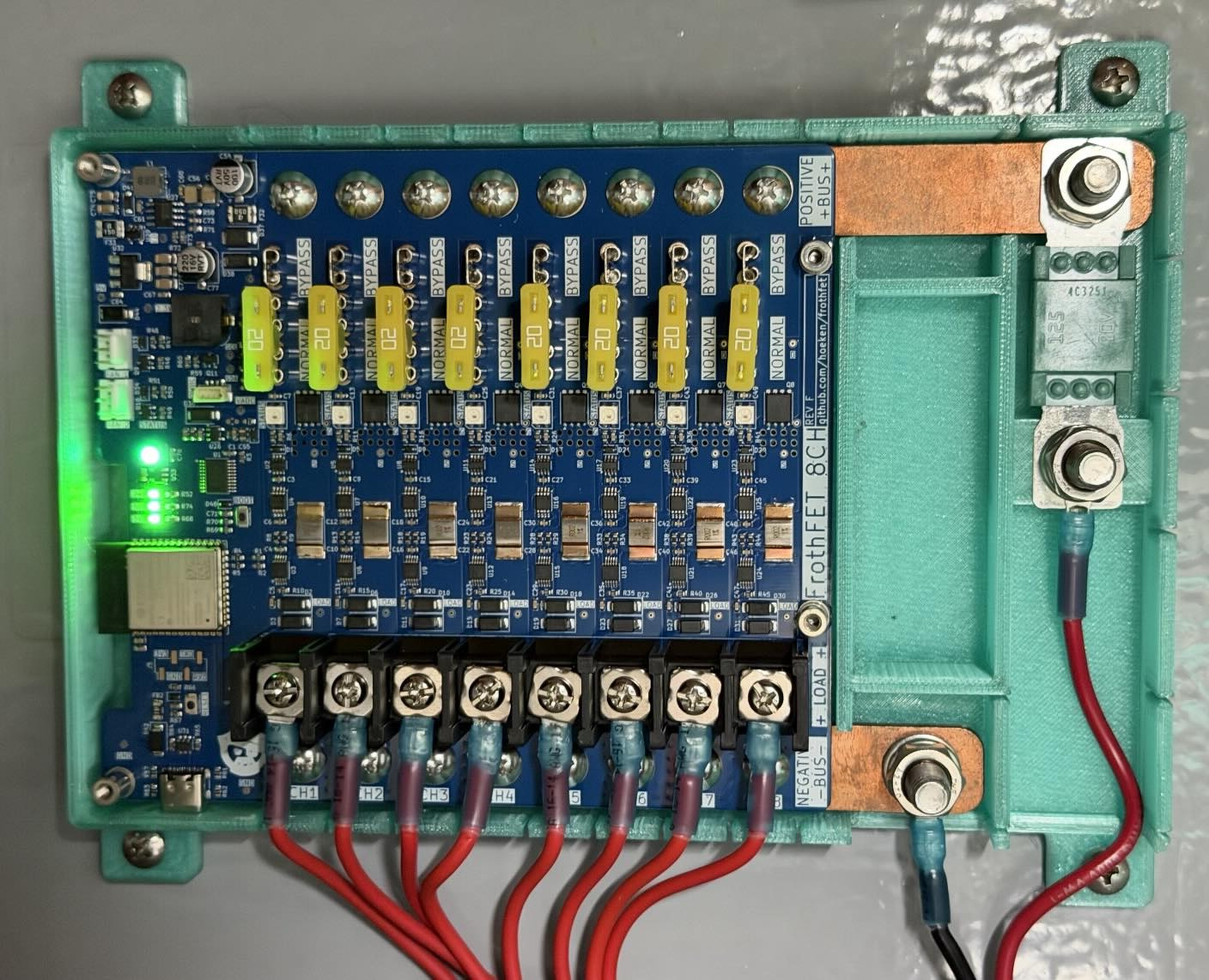
FrothFET has a positive and negative busbar. The positive busbar is longer than the negative busbar. On each busbar is a M8 bolt for attaching the main power cables. The positive connection can also be fitted with a MEGA fuse.
Each busbar also has 8 connections to the board via M4 screws. These screws are connected directly to the busbar and can be used for wiring your system. DC loads can be grounded to an external ground, or wired to the bus bar connection for each channel.
FrothFET does NOT have reverse polarity protection, so it is essential to make sure you do not mix up the positive and negative connections when powering the board.
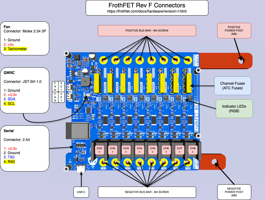
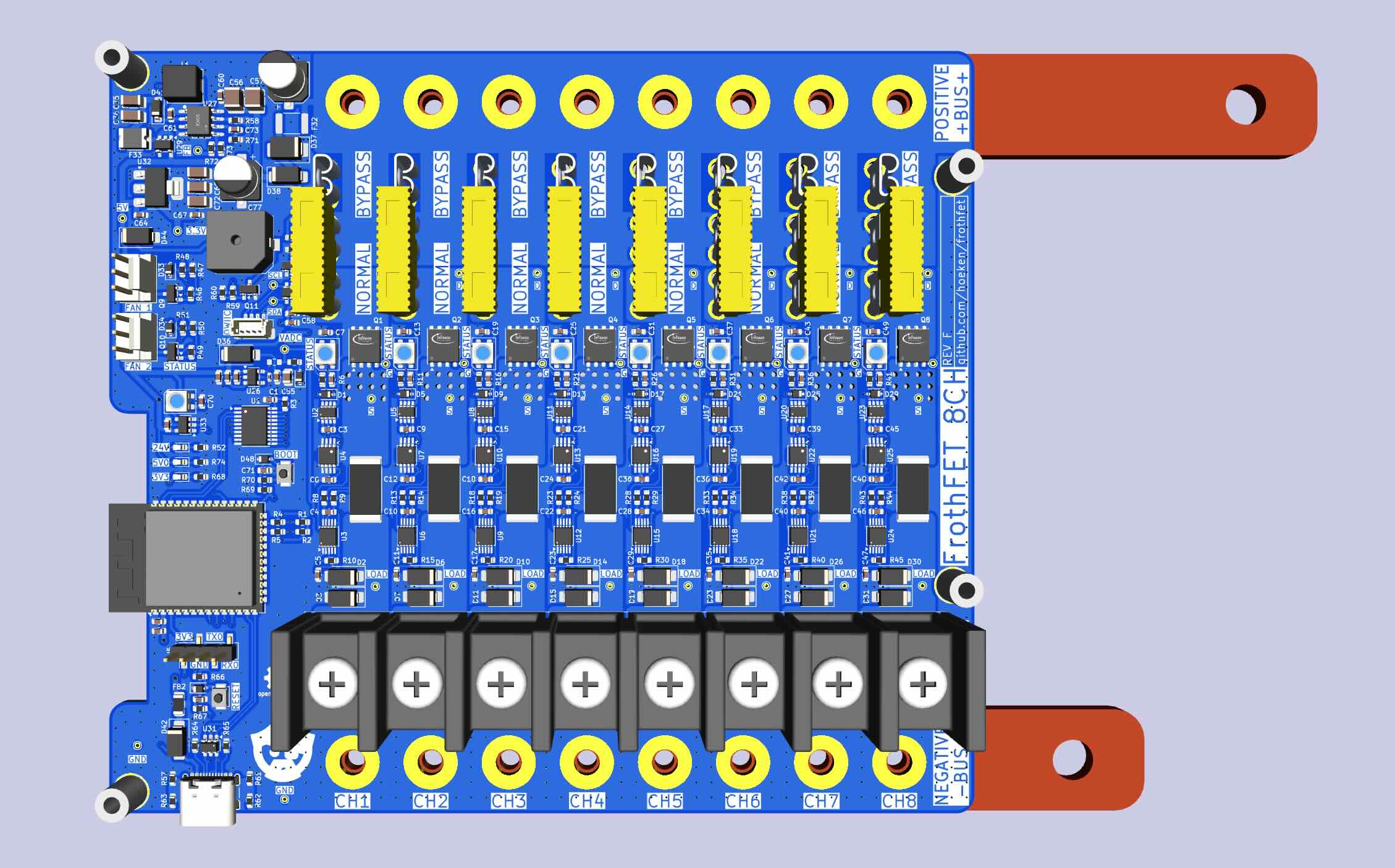
Rev F Pinout (click to enlarge)
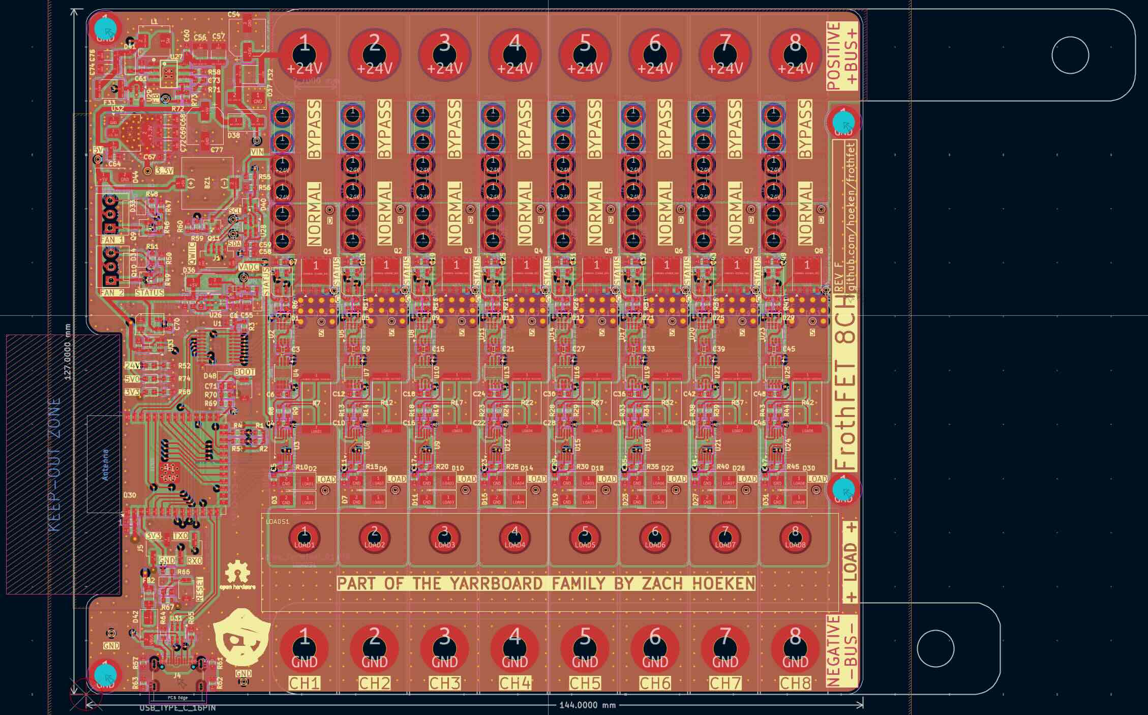
PCB Layout - Rev F
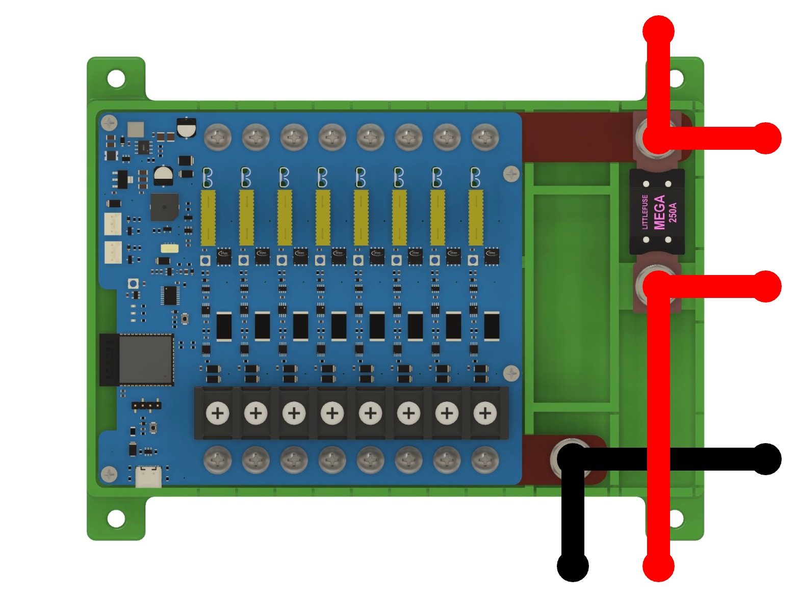
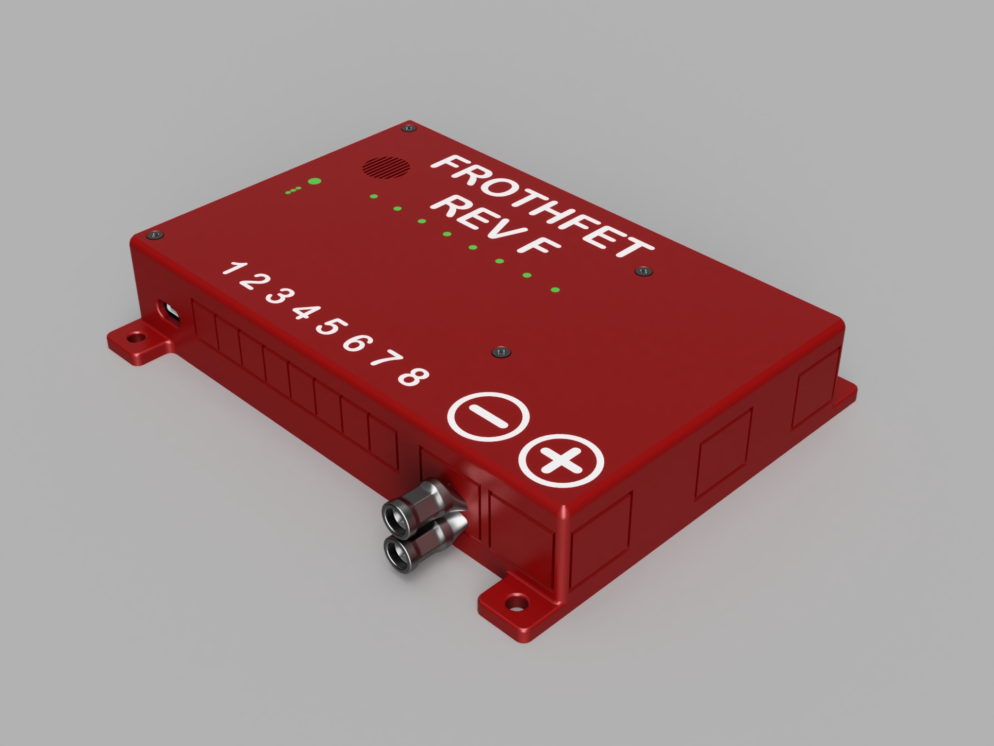
3D Render - Rev F
3D Printable Case
Source Files
Manufacturing
If you would like to manufacture your own boards, follow the instructions below:
Kicad File Preparation
- Install the Kicad
Fabrication Toolkitplugin. - From the PCB Editor, open
Tools -> External Plugins -> Fabrication Toolkit - Click
Generateto create the production files. - Upload the {board_name}.zip file in the first step of the JLC ordering process
- {board_name}_bom.csv file is the Bill of Materials for PCBA
- {board_name}_positions.csv file is the Component Placement file for PCBA
JLCPCB Ordering Options
If no option is specified below, use the default options provided by JLCPCB.
PCB
- PCB Color: Blue
- Surface Finish: ENIG
- Copper Weight: 2oz
Assembly
- Depanel Boards: YES
Busbars
The busbar prototypes were made from lasercut 1/8” (3mm) copper from SendCutSend and hand threaded with a power drill. They could also be CNC cut or even made by hand if you need to. Ideally they would also be tin plated to prevent corrosion.
The design files are located here:
The busbars are also available as STEP files as part of the case design file.
The small holes should be tapped M4 x 0.7mm, the large holes should be tapped M8 x 1.25mm.