Installation
For the installation process, it is best to start the plan on paper. Write out what loads you want to control, their amperages, determine the required fuses and cabling. Once you have that, you can plan your installation location and begin wiring everything up.
Power Cables
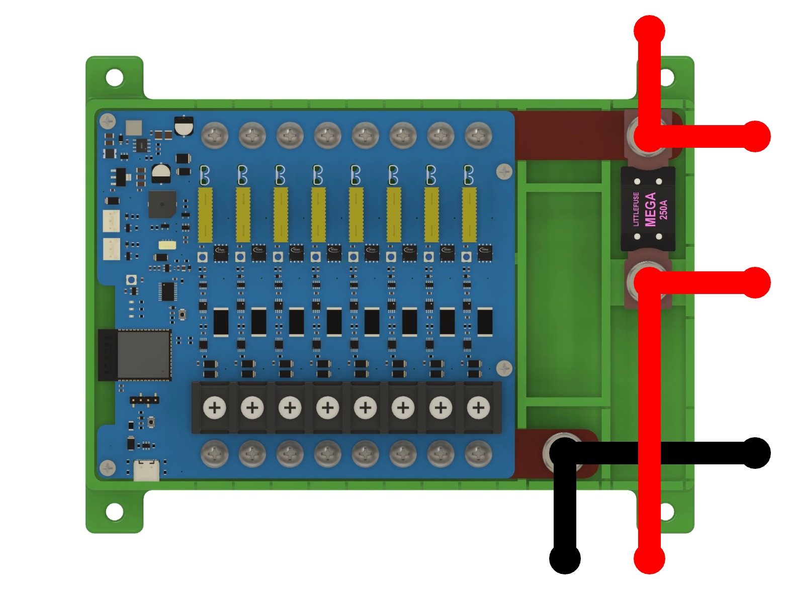
The power cables for the FrothFET board should connect to the M8 (5/16” equivalent) posts on the POSITIVE and NEGATIVE busbars. For 10GA and smaller wires, you can use crimp terminals. For larger wire sizes, it is recommended to use terminal lugs.
Your power cable size for the positive busbar should be chosen based on your maximum total amperage. The fuse should be selected to protect the cable from damage. We highly recommend this wire + fuse selection chart from Blue Sea Systems.
You can optionally have a MEGA fuse on the positive busbar. FrothFET uses standard MEGA fuses for the system fuse.
The maximum recommended amperage for a FrothFET board is 100A.
DC Load Wiring
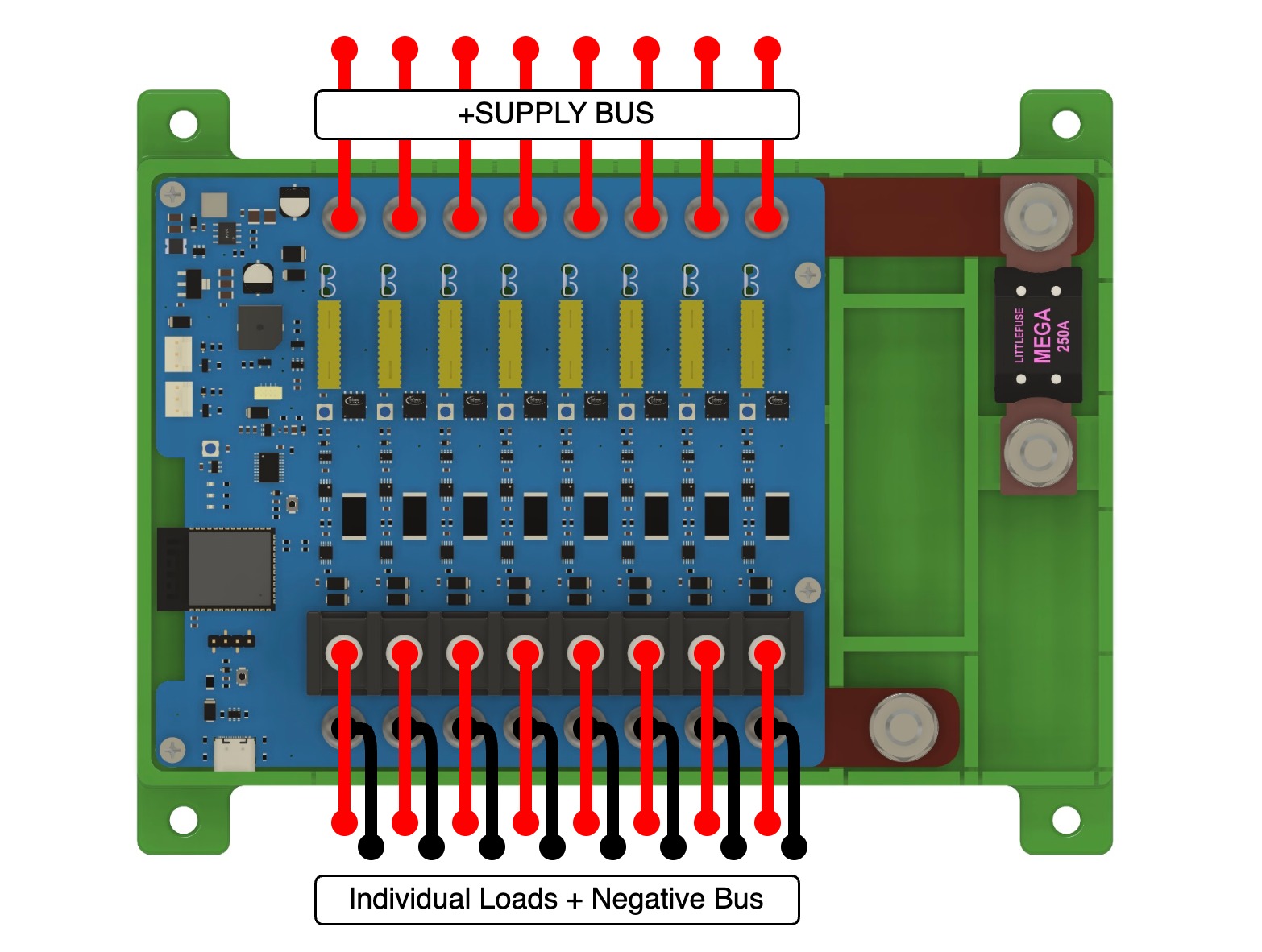
Wiring your DC load is very simple. The POSITIVE wire of your load needs to be connected to the CH+ on your desired channel.
The NEGATIVE wire of your load has two options:
- Connected to the CH# on the FrothFET negative busbar
- An external NEGATIVE busbar (connected to the negative power cable)
Individual channel connections are M4 screws (#8 equivalent). We recommend using marine grade, adhesive lined crimp connectors, either ring or spade (fork) style.
Parallel Bypass (eg. Bilge Pumps)
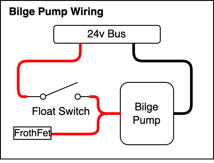
It is possible to wire a switch in parallel to bypass FrothFET if needed. For example, your bilge pumps should be wired with a float switch directly to your supply voltage.
In this type of setup, you can control the bilge pump with FrothFET on demand, but also have it externally controlled with a float switch. FrothFET can detect if a channel is bypassed which allows you to tell if your bilge pump is running.
Wire Routing - Breakaway Tabs
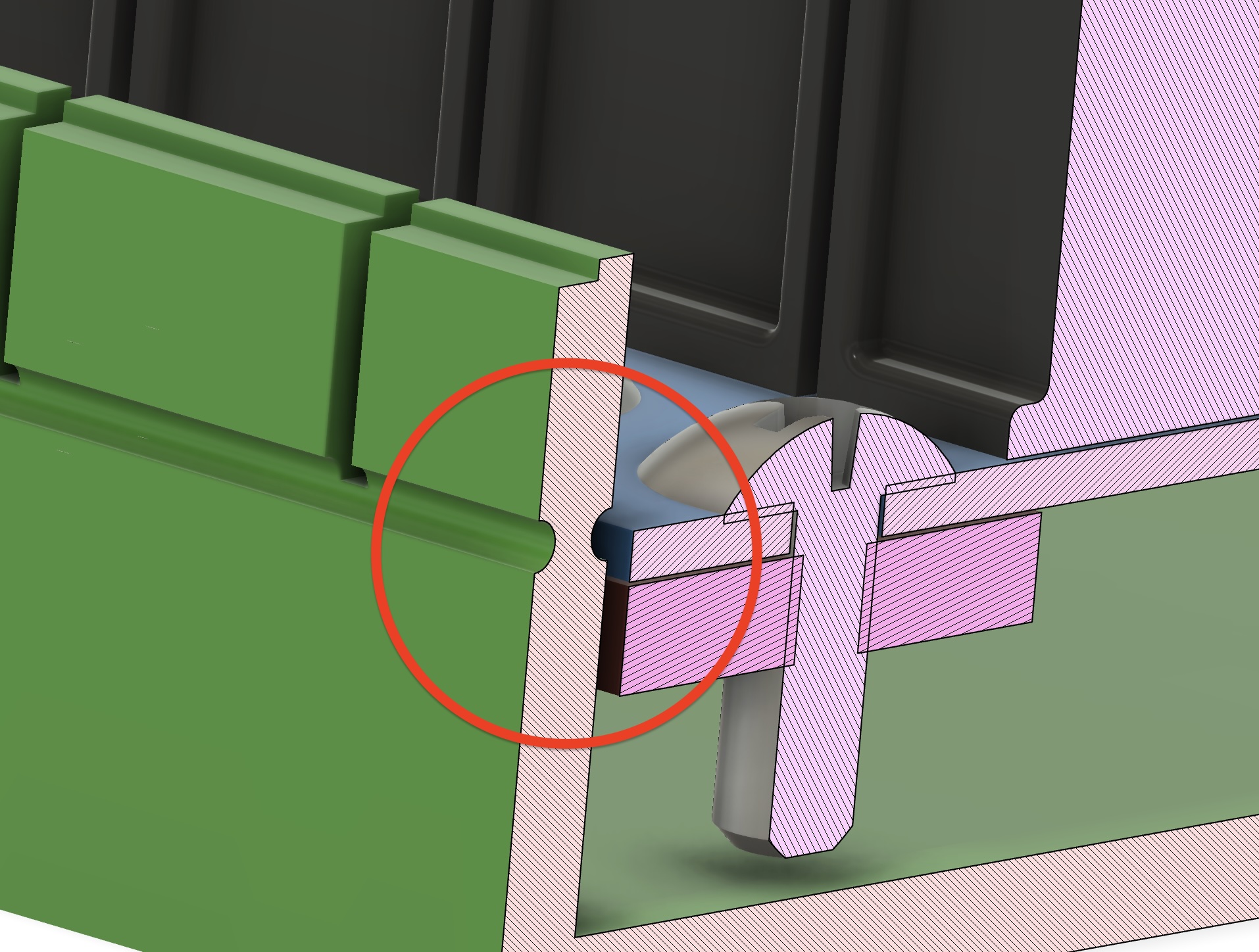
The 3D printed FrothFET case comes with breakaway tabs for each channel, as well as breakaway tabs for the power cables. After you choose what direction you want to route your cables, you can break away the tabs with a pair of pliers. This makes for a clean install, but it is also a safety feature to prevent accidental contact with the terminals.
Fuse Selection
We highly recommend this wire + fuse selection chart from Blue Sea Systems for selecting your wire and fuse size for each load.
FrothFET uses standard ATC fuses for each channel.
The maximum amperage for each channel is 20A.
Fuse Bypass Mode
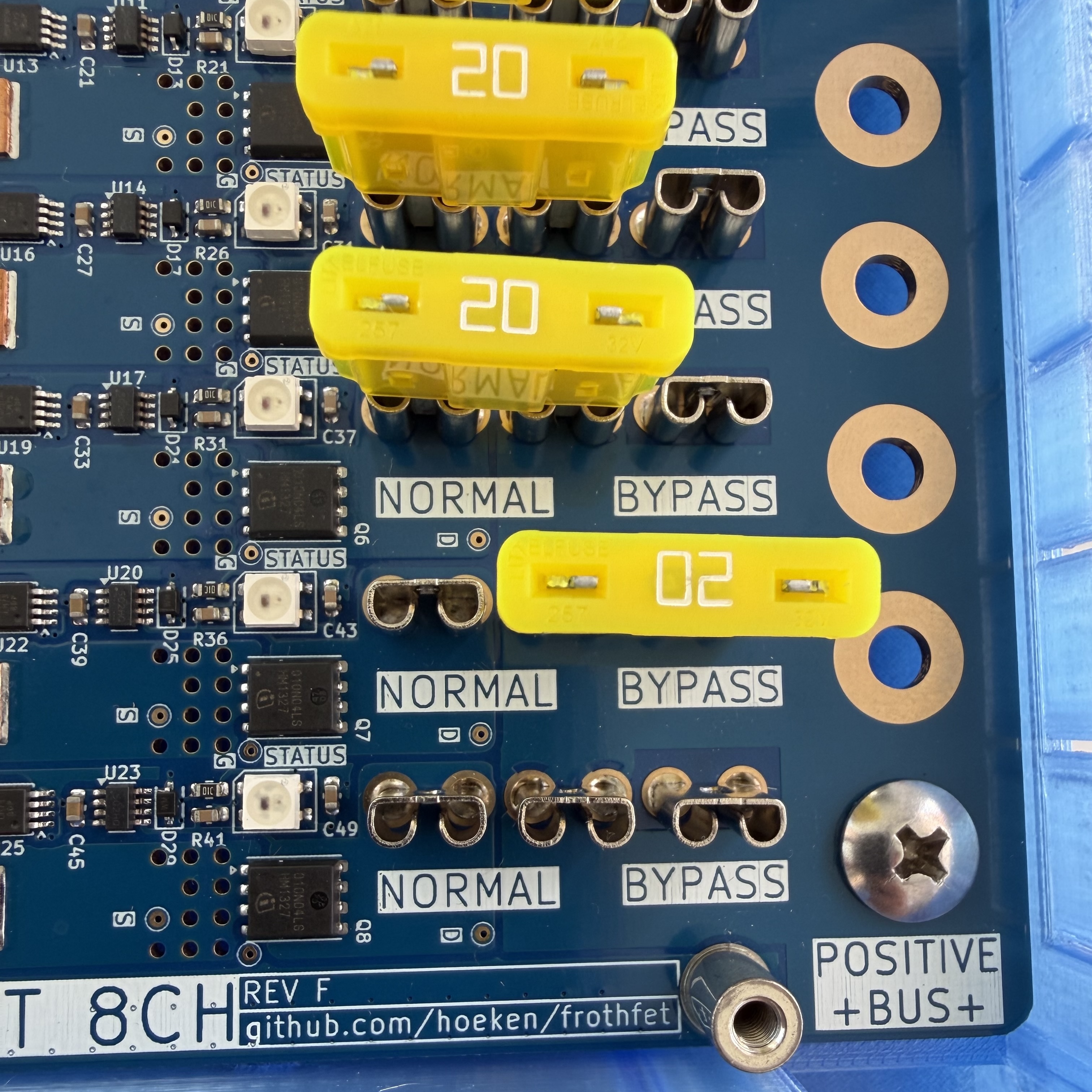
When installing the fuse, note there are two possible positions: NORMAL and BYPASS. Normal mode is the position for standard operation. In case of electronics failure, you can move the fuse to BYPASS mode which will connect the load directly to your supply voltage, bypassing FrothFET control.
Indicator LEDs
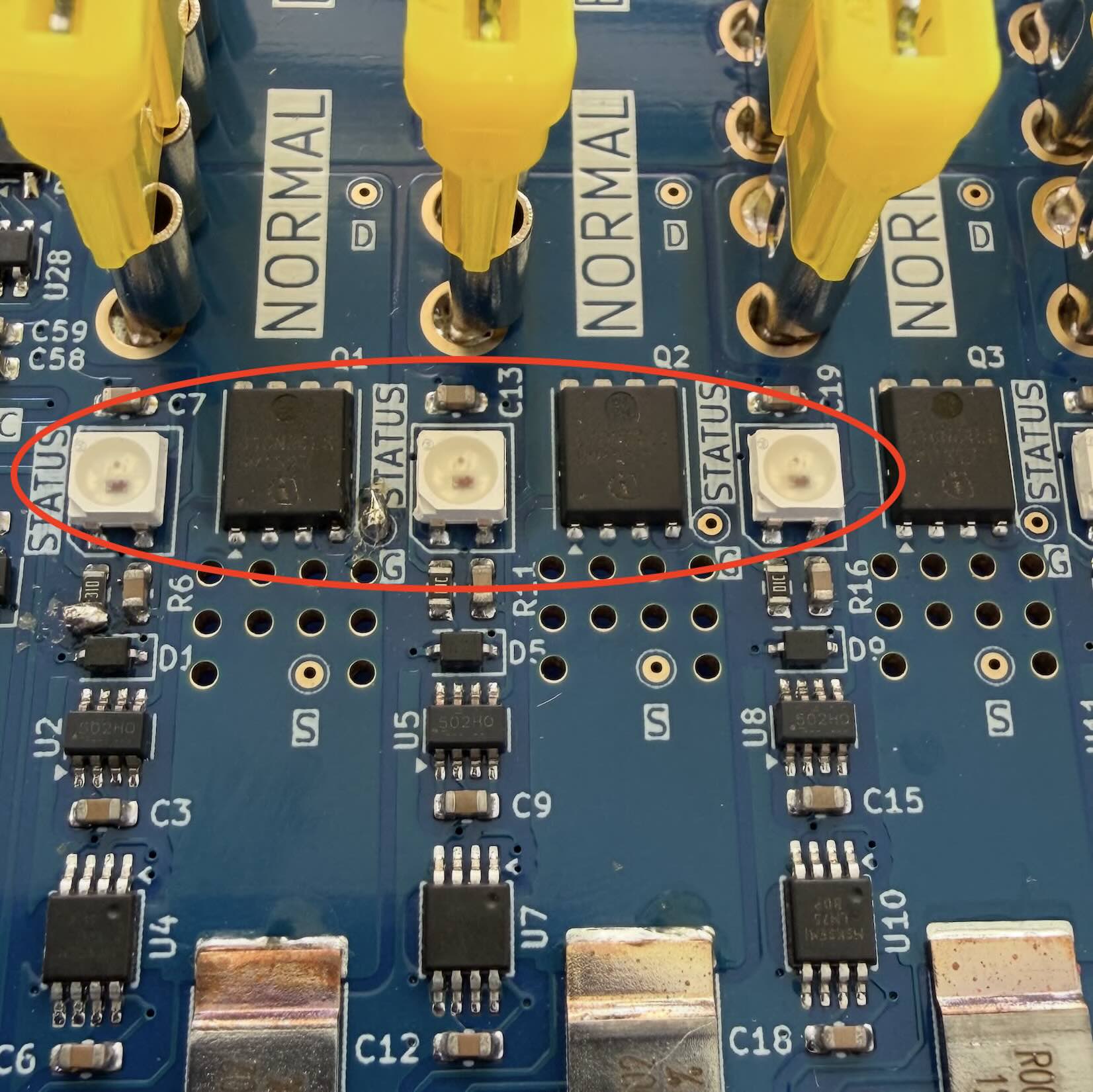
Each channel has an RGB led located next to the fuse. This LED will change color to show the current status of the channel.
- OFF
- ON
- BYPASSED
- TRIPPED
- BLOWN
- OVERHEAT
Cooling Fans
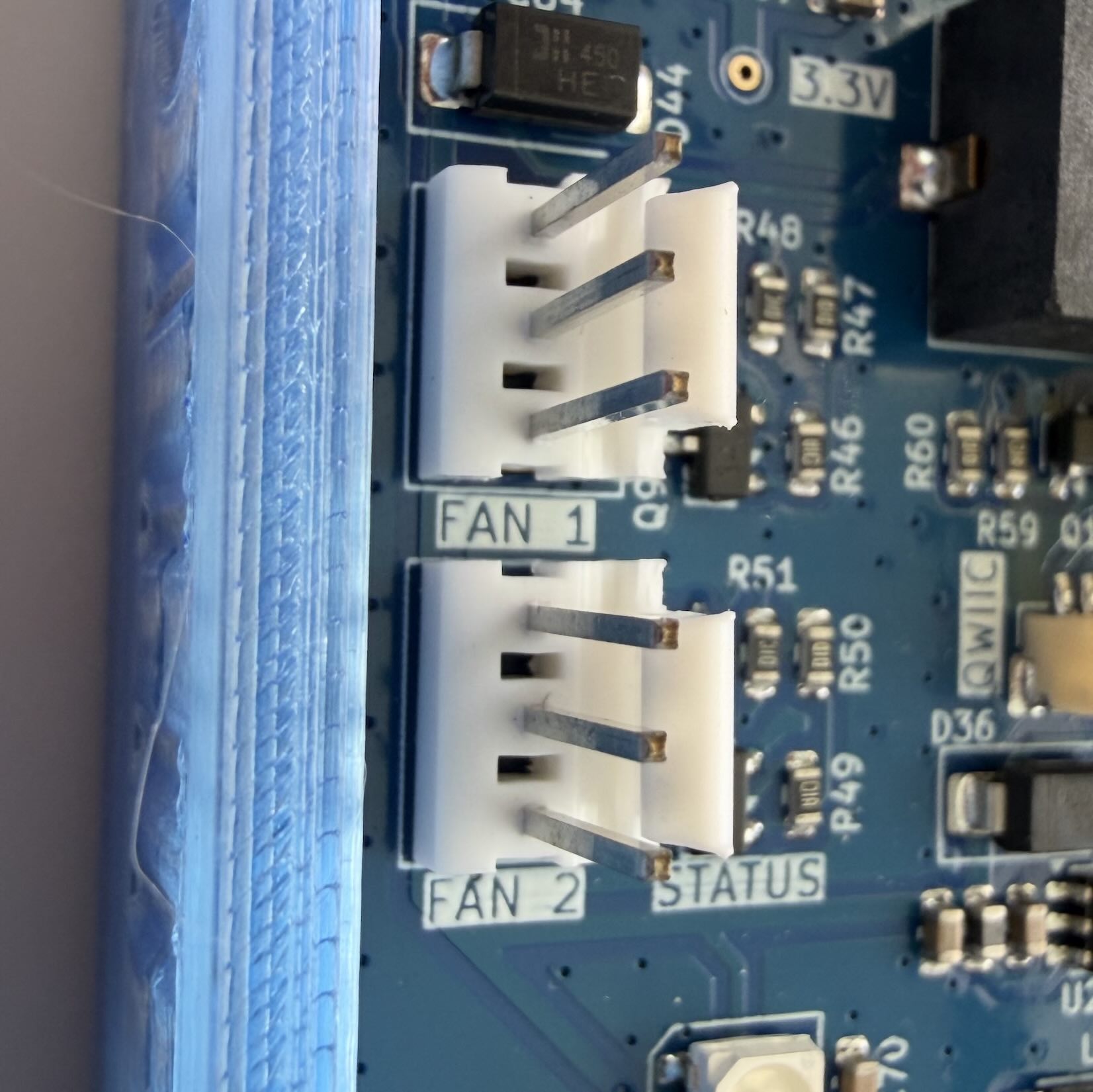
FrothFET has two headers for standard 5v DC fans that can be used for cooling of the electronics during high loads. Each channel is equipped with a temperature sensor, so the fans will turn on and off automatically.
Configuration
After wiring your loads to FrothFET, you will need to configure each channel. Open the web UI to Settings -> PWM Channels. See the Software Configuration section for more information.